
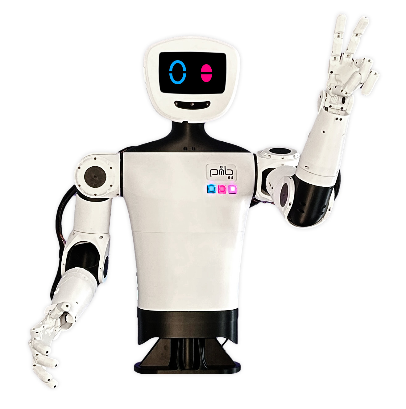
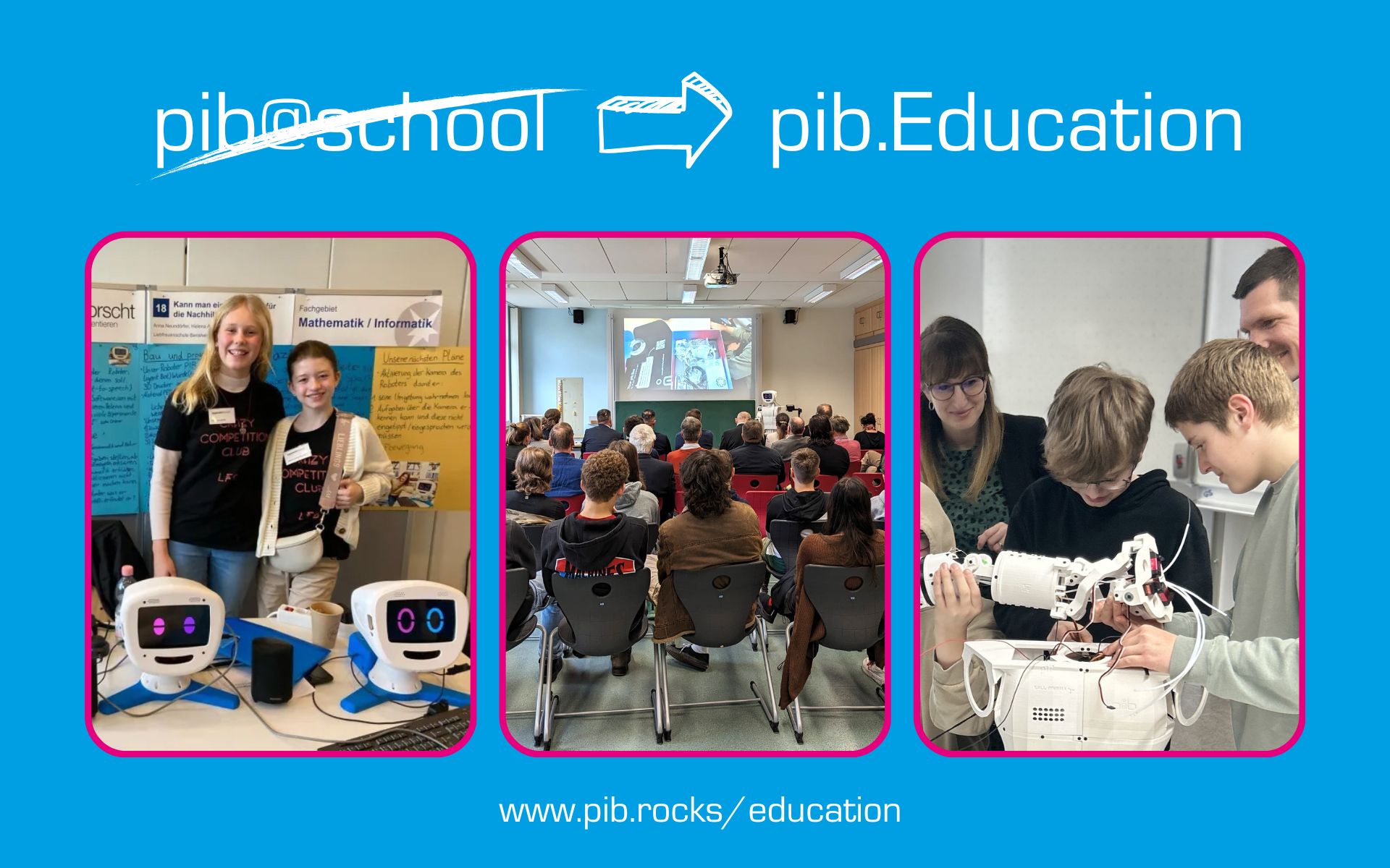
YOUR OWN ROBOT


pib kann jeden inspirieren.
Für wen ist pib interessant?


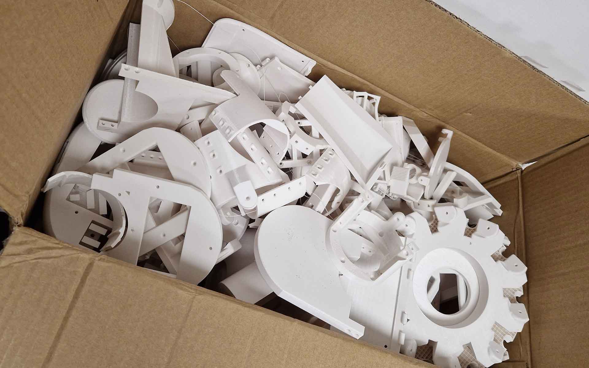
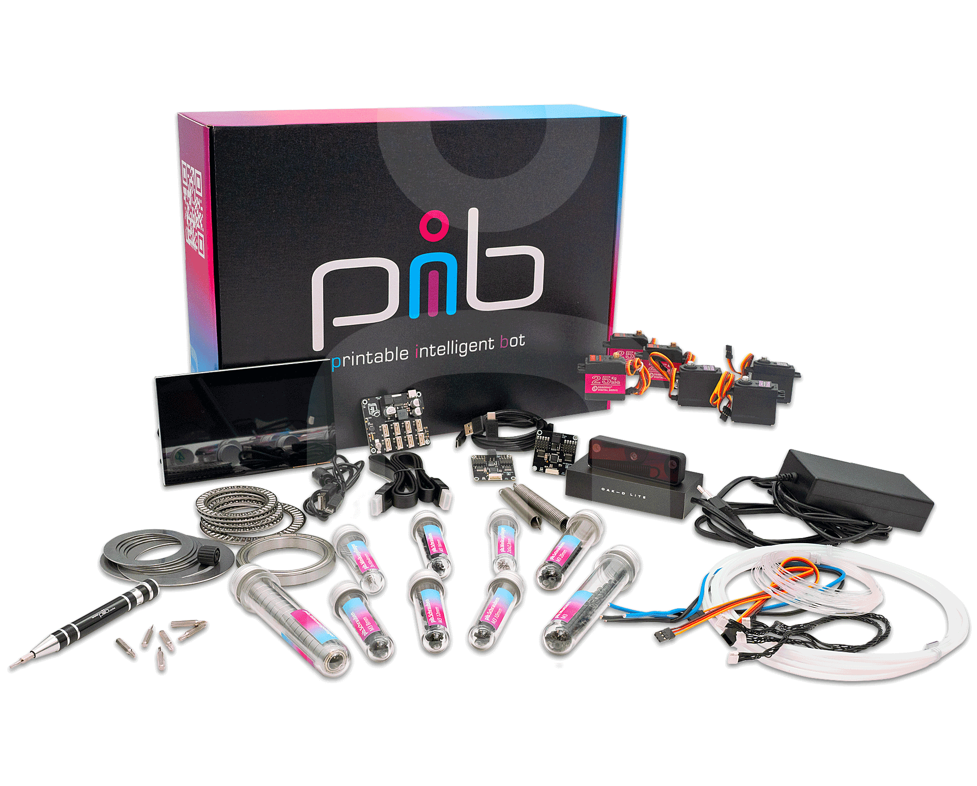 Du willst deinen pib selbst zusammenbauen und brauchst noch die richtigen Schrauben, Motoren und elektronischen Bauteile? In unserem pib.Shop findest du komplette Sets mit allen nicht druckbaren Teilen, die du brauchst, um deinen eigenen humanoiden Roboter zu bauen. Beginne noch heute mit dem Zusammenbau!
 We nn deine
  Komm auf unseren Discord-Server, um die neuesten Nachrichten über pib zu erfahren und Teil unserer Community zu werden. Tausche dich mit anderen Makern und 3D-Druckfans oder Robotik-Enthusiasten aus. Teile deine Ideen und deine Fortschritte!
pib berichtet über die neuesten Nachrichten.
Messen, Auszeichnungen, neue Funktionen und vieles mehr.

pib geht um die Welt
Wenn du auch an pib arbeitest, aber deine Stadt noch nicht auf unserer Karte findest, schicke uns eine Nachricht!
Sie sehen gerade einen Platzhalterinhalt von Google Maps. Um auf den eigentlichen Inhalt zuzugreifen, klicken Sie auf die Schaltfläche unten. Bitte beachten Sie, dass dabei Daten an Drittanbieter weitergegeben werden.
Mehr Informationen